A lot of work has been done on refining the activator into something more practical. It's now smaller, automatic (no buttons needed), and mounts on the chain stay. Here's a picture:
You can follow the progress at VeloLoop.com.
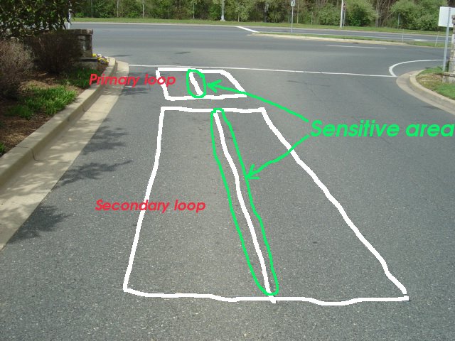
A common problem for bicyclists, and in particular for bicycle commuters, is the traffic loop sensor. These are the devices which detect the presence of vehicles to control the sequencing of traffic lights at many intersections. Often, they are installed in figure-eight slits cut into the pavement near a traffic light:
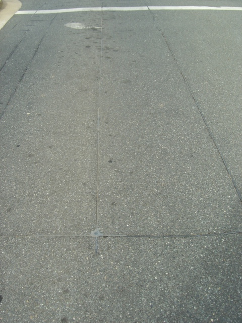
The way they work is to detect the slight change in inductance of the loop of wire buried in the slit caused by a large metallic object (such as a motor vehicle) above the loop. This is usually accomplished by sensing the change in frequency of a free-running oscillator which is directly connected to the loop. As the loop inductance changes, so does the frequency. The problem for bicyclists is that, although many sensors are sufficiently sensitive to detect a bicycle, traffic departments often feel compelled to set the sensitivity of the electronics behind the loop rather low, so that false detections are avoided. This can make it difficult at some intersections for a bicycle (a relatively small metal object) to make its presence known to the sequencing circuit. The result is a lot of frustration for a bicyclist trying to get a green light or left-turn arrow. This can be especially frustrating at streets with low traffic (often where these sensors are used in the first place), as one waits for a motor vehicle to come by and trip the sensor. Sometimes one must resort to laying the bicycle down on the road surface above the loop with the hope that the extra metal presented to the loop will cause detection. Sometimes it doesn't work, and sometimes frames aren't made of metal.
Various devices have been patented in order to address this problem. Some are a little impractical, and some don't work with modern loop sensor circuitry. One patented solution (see USP 5,652,577) has the bicyclist laying down a big piece of metallic foil or screen right on the road surface!
A popular myth is that a strong permanent magnet will do the trick. This is complete nonsense, since a magnet produces a constant (D.C.) field and can not change the inductance of the sensor loop, nor can it in any way pull the frequency of the sensor's oscillator. One must inject a signal at or near the operating frequency of the loop in order to cause the sensor to notice a change. Although some will swear that their magnet is effective, it is possible that they have found a sensitive sensor, or that (more likely) another vehicle is present on an adjacent or opposite sensor and is activating the light sequence.
After studying this problem for many years, we have developed a new device (It's patented! See USP 7,432,827) designed to be much more effective on a wide variety of loop sensors. It has been developed in two forms:
The first form consists of a small (4 by 5 inches) loop of wire mounted below the crank, some electronics to drive it, and a pushbutton to activate it. Here is a picture of an early prototype, mounted on a bicycle:
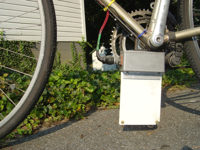
A bracket holds the unit to the frame by attaching to threaded holes normally used for a lower water bottle cage.
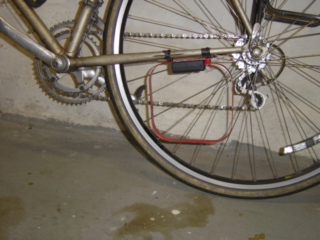
The second form utilizes the metallic tubing of the bicycle frame to form a large loop for magnetic coupling to the traffic sensor. This form consists of an electronics box and a transformer which clamps around the frame, somewhere on the large triangle (see USP 7,907,065). Here is a picture of a prototype, mounted on the top tube:
![]()
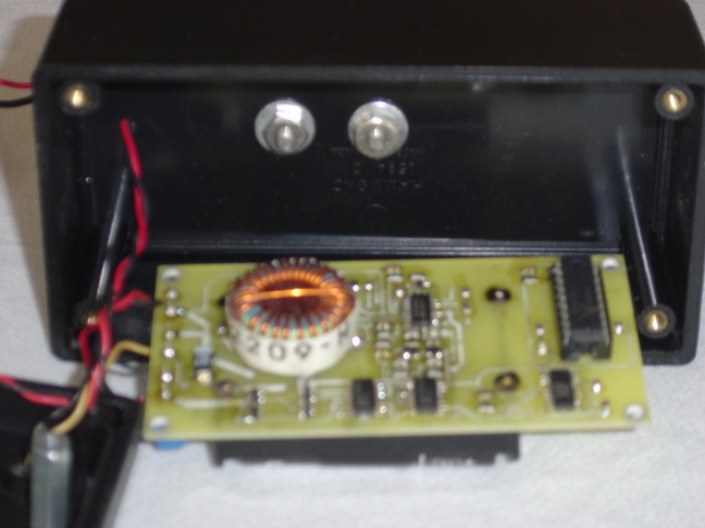
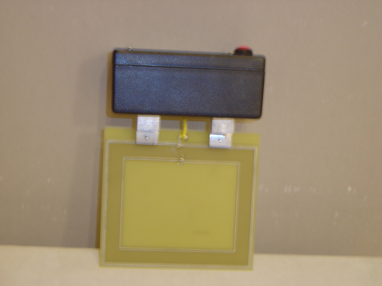
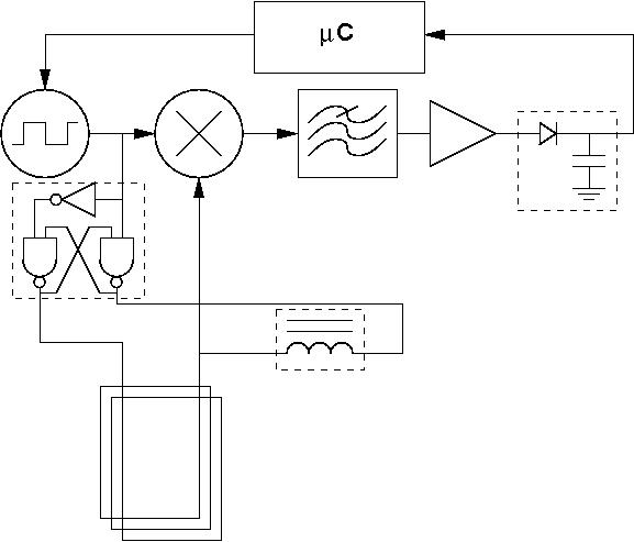
Here is a picture of a newer prototype, made portable for demonstrations, and a diagram showing a little bit of how the electronics works:
| 
|
In practice, there are some important considerations:
There is so much variation in activation requirements that one must become familiar with each intersection in order to trigger presence using the electronic device in a way that minimizes battery drain.
The activator does not necessarily cause an immediate change in the traffic light status, and does not pre-empt the light. It does not let you "run" the light. Rather, it creates the same effect as an automobile creates in that it starts the programmed timing sequence for that intersection. The timing of that sequence can be very different at different intersections. The activator creates an indication of presence of a vehicle. You may still have to wait a bit for the light to change, depending on that sequence. However, you will eventually get the signal, just as a car would. Traffic laws still apply.
You can read some manuals for one brand of inductive traffic loop detectors here (Eberle Design, Inc.).
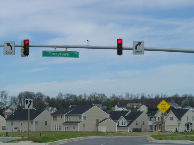
Inductive loop sensors often fail due to crushing forces beneath the pavement causing the loop wires to break. As one can imagine, this can produce a maintenance nightmare. This is the main reason why, over the last decade or so, inductive loop-based sensors are being replaced or passed over in favor of visual systems. These rely on cameras mounted on traffic light poles and detect presence by the use of image recognition software. The are looking for a large enough change in the image to indicate that a vehicle is present. These are becoming very common, although by no means universal, and can be spotted at many major intersections:
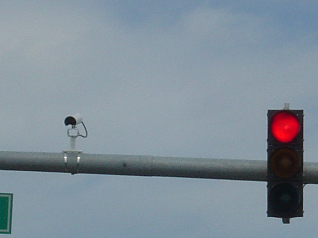
These visual sensors can be more difficult for a bicyclist than the older loop sensor technology. The visual sensor, especially when mounted far from where the bicyclist is waiting (such as across a 4-lane highway) can often not detect the presence of something as small as a bicycle/rider. One can wave arms, a jacket, or, that failing, wait for a motor vehicle. At night, sometimes a bicycle headlight pointed directly into the camera will work. In many cases, though, these can be nearly impossible to activate.
On the brighter side, many traffic departments are discovering that the visual sensors can fail to detect motor vehicles when their color too closely matches that of the background. Some departments have reverted back to loop sensors, and some will install both types of sensor in order to increase reliability. Also encouraging is the emergence of infallible sensor loops which should keep the inductive loop sensor with us for a long time.
If interested, you can send mail.
Proud to support:
![]()